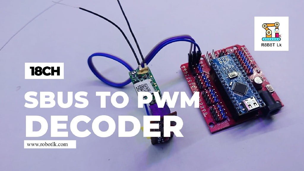
In this tutorial, we will learn how to decode an SBUS signal into 18 PWM channels. This can be utilized for drones, RC cars, and robotics. Additionally, a significant number of PWM outputs are required for remotely controlling robot creations employing servo motors, with a total of eighteen PWM outputs available here.
You can watch the following video or read the written tutorial below.
Overview
SBUS (Serial Bus) is a digital communication protocol used in radio control systems. This can be utilized for drones, RC cars, and robotics. Additionally, a significant number of PWM outputs are required for remotely controlling robot creations employing servo motors, with a total of eighteen PWM outputs available here.
The table below shows how to get PWM Output 18 from the Digital and Analog pins of the Arduino board
| Arduino | PWM Channel |
|---|---|
| D2 | CH1 |
| D3 | CH2 |
| D4 | CH3 |
| D5 | CH4 |
| D6 | CH5 |
| D7 | CH6 |
| D8 | CH7 |
| D9 | CH8 |
| D9 | CH9 |
| D10 | CH10 |
| D11 | CH11 |
| D12 | CH12 |
| D13 | CH13 |
| A0 | CH14 |
| A1 | CH15 |
| A2 | CH16 |
| A3 | CH17 |
| A4 | CH18 |
What is the SBUS Protocol?
SBUS, which stands for Serial BUS, is a digital communication protocol commonly used in the field of radio control (RC) systems. Developed by Futaba, a leading manufacturer of RC equipment, SBUS is designed to transmit multiple channels of information over a single wire. The protocol enables the bidirectional communication between the RC receiver and the transmitter, allowing for more efficient and reliable control of model vehicles such as drones, airplanes, helicopters, and cars.
Key features of the SBUS protocol include
- Digital Transmission: SBUS employs a digital signal, which enhances precision and reduces the risk of signal interference compared to traditional analog systems.
- Multiple Channels: SBUS can transmit multiple channels of control data over a single connection. This is particularly advantageous in applications where a large number of control channels are required, such as complex drones or robotic systems.
- Reduced Wiring: By consolidating multiple channels into a single wire, SBUS simplifies wiring setups, reducing the complexity of connections between the receiver and other components.
- High Resolution: SBUS provides high resolution and low latency, allowing for precise and responsive control of RC models.
- Bi-Directional Communication: SBUS supports bidirectional communication, enabling the receiver to send feedback information to the transmitter. This feature can be used for telemetry data, allowing the operator to monitor various parameters of the model vehicle in real-time.
- Compatibility: While Futaba initially developed SBUS, it has gained widespread adoption, and many other RC manufacturers offer compatibility with the SBUS protocol.
To implement SBUS communication in a system, users typically require an SBUS-compatible transmitter, receiver, and, if needed, an SBUS-to-PWM converter for interfacing with devices that use PWM signals. Arduino and other microcontrollers can be programmed to decode SBUS signals for various applications in robotics and RC projects.
Components Needed
Before we begin, make sure you have gathered all the necessary components. The purchase links are in the description of my YouTube video.
- Arduino NANO
- IO Expansion Module for Arduino Nano
- SBUS Receiver ( I am using FrSky Xm+ SBUS receiver )
- transmitter ( A transmitter that matches the receiver- I am using Jumper T-lite Transmitter )
- Dot Board
- BC547 NPN Transistor
- 10K Ohms resistor
- 4.7K Ohms resistor
- Female header ( 3Pin )
- Male header (3Pin )
- Jumper Wires
- Two 18650 Li-ion Battery.
- Two cell 18650 Li-ion battery holder
- SG90 servo motor ( To check if the PWM Output is working correctly )

How to amplify a SBUS signal using NPN transistor?
Amplifying an SBUS signal to connect to the RX pin of an Arduino involves considerations of the SBUS signal’s characteristics, which is typically a digital signal. The goal might be more about signal conditioning or level-shifting rather than traditional analog amplification. Below is a guide on how to interface an SBUS signal with a NPN transistor and connect it to the RX pin of an Arduino using the provided components:
Components Needed:
- SBUS Signal Source (Connects to RX pin of Arduino)
- NPN Transistor (e.g., BC547)
- 10kΩ Resistor (R1)
- 4.7kΩ Resistor (R2)
Circuit Configuration
- Connect the emitter (E) of the BC547 to the ground (GND).
- Connect the collector (C) of the BC547 to the positive supply voltage (Vcc). This is usually the 5V rail of your Arduino.
- Connect the base (B) of the BC547 to the SBUS signal source through the 10kΩ resistor (R1).
- Connect the junction between the base and the 10kΩ resistor to the junction of the 4.7kΩ resistor (R2. Connect the other end of R2 to the Vcc.
- Connect the RX pin of the Arduino to the junction between the collector of the BC547 and the output load.

Circuit Diagram
The next stage is connecting the electronics. The circuit diagram of this project is actually quite simple. As depicted in the circuit diagram, the procedure for connecting the module wires is further explained below. You can download this circuit diagram. For that, click on the download below and download it.

Connect the Arduino Nano board to the IO Expansion Shield
Arduino Nano IO Expansion Shield is used to get PWM output easily. Servo motors are often controlled by PWM output. Servo motors can be connected directly when using the Arduino Nano IO Expansion Shield. Secure the IO Expansion Shield onto the Arduino Nano. Confirm that the pins align correctly for a stable connection. The expansion shield simplifies interaction with the servo motors and other components, enhancing the project’s flexibility.

Connecting the SBUS signal Amplifying circuit to the Arduino Nano IO Expansion Shield
I made a small SBUS signal amplifying circuit. You can also make it small by watching the YouTube video. Do not connect the SBUS receiver to this. Before that, connect it to the IO Expansion Shield and upload the code.


- Connect GND to Rx G Pin on the io expansion board.
- Connect 5V to Rx V Pin on the io expansion board.
- Connect Inverter Signal Pin to Rx S Pin on the io expansion board. Connect GND to Rx G Pin on the io expansion board.
- Connect 5V to Rx V Pin on the io expansion board.
- Connect Inverter Signal Pin to Rx S Pin on the io expansion board.
Uploading the code to the Arduino Nano board.
Copy the following Arduino code and paste it into the new sketch in the Arduino IDE. Select the board and port and upload the code. If this is difficult to do, watch a tutorial video.
You can download the Arduino code and open it directly through the Arduino IDE. Click the Download button below to download the Arduino code
#define MAX_GROUP_TIME 24138

uint8_t frame[24];
uint16_t dTimes[6];
uint16_t bTimes[6];
uint16_t cTimes[6];
uint16_t maxTime = 18000;

void setup() {
  Serial.begin(100000, SERIAL_8E2);
  PORTD = 0b00000000; //  1st 6 PWM channel outputs on D2-D7
  DDRD  = 0b11111100;
  PORTB = 0b00000000; // next 6 PWM channel outputs on D8-D13
  DDRB  = 0b00111111;
  PORTC = 0b00000000; // last 6 PWM channel outputs on A0-A5
  DDRC  = 0b00111111;


  TCCR1A = 0x00;
  TCCR1B = 0x02;
}

void loop() {
  while(Serial.available()) {

    int b = Serial.read();
    if (b != 0x0F) {
      continue;
    }
    frame[23] = 0xFF;
    int i = 0;
    while (i < 24) {
      i += Serial.readBytes(frame + i, min(Serial.available(), 24 - i));
    }
    if (i == 24 && frame[23] == 0x000) {
      uint16_t edgeTime = 0;
      for (uint8_t ch = 0; ch < 6; ch++) {
        edgeTime += channel(ch) + 1976;
        dTimes[ch] = edgeTime;
      }
      edgeTime = 0;
      for (uint8_t ch = 6; ch < 12; ch++) {
        edgeTime += channel(ch) + 1976;
        bTimes[ch - 6] = edgeTime;
      }
      edgeTime = 0;
      for (uint8_t ch = 12; ch < 16; ch++) {
        edgeTime += channel(ch) + 1976;
        cTimes[ch - 12] = edgeTime;
      }
      edgeTime += frame[22] & 0x01 ? 4023 : 1976;
      cTimes[4] = edgeTime;
      edgeTime += frame[22] & 0x02 ? 4023 : 1976;
      cTimes[5] = edgeTime;

      uint8_t dIndex = 0;
      uint8_t dMask = 0b00000100;
      uint16_t dTime = dTimes[dIndex];
      uint8_t bIndex = 0;
      uint8_t bMask = 0b00000001;
      uint16_t bTime = bTimes[bIndex];
      uint8_t cIndex = 0;
      uint8_t cMask = 0b00000001;
      uint16_t cTime = cTimes[cIndex];

      uint16_t currentTimer = 0;
      PORTD = dMask;
      PORTB = bMask;
      PORTC = cMask;
      TCNT1 = 0;
      while (currentTimer < MAX_GROUP_TIME) {
        if (dIndex < 6 && currentTimer > dTime) {
          dMask <<= 1;
          PORTD = dMask;
          dIndex++;
          dTime = dTimes[dIndex];
        }
        if (bIndex < 6 && currentTimer > bTime) {
          bMask <<= 1;
          PORTB = bMask;
          bIndex++;
          bTime = bTimes[bIndex];
        }
        if (cIndex < 6 && currentTimer > cTime) {
          cMask <<= 1;
          PORTC = cMask;
          cIndex++;
          cTime = cTimes[cIndex];
        }
        currentTimer = TCNT1;
      }
      PORTD = PORTB = PORTC = 0b00000000;

      while (Serial.available()) {
         Serial.read();
      }
      break;
    }
  }
}

uint16_t channel(uint8_t ch) {
  uint8_t k = ch > 7 ? 11 : 0;
  switch (ch % 8) {
    case 0:
      return (uint16_t)frame[0+k] | ((((uint16_t)frame[1+k]) & 0x07) << 8);
    case 1:
      return ((uint16_t)(frame[1+k] & 0xF8) >> 3) | ((((uint16_t)frame[2+k]) & 0x3F) << 5);
    case 2:
      return ((uint16_t)(frame[2+k] & 0xC0) >> 6) | ((((uint16_t)frame[3+k])) << 2) | ((((uint16_t)frame[4+k]) & 0x01) << 10);
    case 3:
      return ((uint16_t)(frame[4+k] & 0xFE) >> 1) | ((((uint16_t)frame[5+k]) & 0x0F) << 7);
    case 4:
      return ((uint16_t)(frame[5+k] & 0xF0) >> 4) | ((((uint16_t)frame[6+k]) & 0x7F) << 4);
    case 5:
      return ((uint16_t)(frame[6+k] & 0x80) >> 7) | ((((uint16_t)frame[7+k])) << 1) | ((((uint16_t)frame[8+k]) & 0x03) << 9);
    case 6:
      return ((uint16_t)(frame[8+k] & 0xFC) >> 2) | ((((uint16_t)frame[9+k]) & 0x1F) << 6);
    case 7:
      return ((uint16_t)(frame[9+k] & 0xE0) >> 5) | (((uint16_t)frame[10+k]) << 3);
  }
  return 0xFFFF;
}
Connecting the SBUS receiver.
After uploading the code to the Arduino Nano board, connect the SBUS receiver to the signal inverter.

Connecting power to the SBUS to PWM Decoder
The power input plug of the Arduino NANO IO Expansion Shield is powered by a DC Male Jack. I use two 18650 Li-ion batteries for it.

Check if the PWM Output is working
To confirm the functionality of the PWM output, start by binding the SBUS receiver and transmitter. Refer to external resources or conduct a Google search for specific instructions on how to perform the binding process for your particular transmitter and receiver model.
Verify if the PWM channel is functioning by testing it with a servo motor. You can comprehend the procedure by watching the video. The table below shows how to get PWM Output 18 from the Digital and Analog pins of the Arduino board.
| Arduino | PWM Channel |
|---|---|
| D2 | CH1 |
| D3 | CH2 |
| D4 | CH3 |
| D5 | CH4 |
| D6 | CH5 |
| D7 | CH6 |
| D8 | CH7 |
| D9 | CH8 |
| D9 | CH9 |
| D10 | CH10 |
| D11 | CH11 |
| D12 | CH12 |
| D13 | CH13 |
| A0 | CH14 |
| A1 | CH15 |
| A2 | CH16 |
| A3 | CH17 |
| A4 | CH18 |

Conclusion
In conclusion, this comprehensive tutorial has guided through the process of decoding an SBUS signal into PWM channels for effective control of servo motors, particularly applicable in drones, RC cars, and robotics. The SBUS signal amplifying circuit, coupled with the Arduino Nano IO Expansion Shield, provides an efficient interface for decoding and processing the SBUS signal. By connecting the SBUS receiver and uploading the corresponding code to the Arduino Nano, the system becomes capable of interpreting and utilizing the PWM outputs. The integration of power through two 18650 Li-ion batteries ensures a reliable and portable power source. Verification of PWM functionality is achieved through binding the transmitter and receiver, followed by testing with a servo motor. This tutorial, enriched with explanatory details and external resources such as videos, equips enthusiasts and engineers with the knowledge and skills necessary for successful implementation and utilization of SBUS signal decoding in a variety of robotics and RC applications.


